Co-rotating intermeshing twin-screw extruders (TSEs) are the most common equipment used in the compounding industry for the continuous mixing of polymers with additives and fillers. This type of machine also processes many formulations using atypical active ingredients.
But we must be aware that materials exposed to high shear and high temperatures are very susceptible to degradation, so almost every product benefits from strategically managing how to transfer shear (and energy) to the material being processed and measuring the resulting melt temperature.
Many factors can affect and control the melt temperature. In this article, the focus will be on the OD/ID ratio, melt zone in the screw, and front-end design.
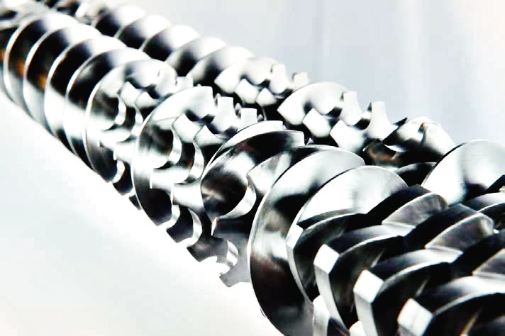
Melting theory and design basis of Co-rotating intermeshing twin-screw extruders
The co-rotating intermeshing twin-screw extruders use a segmented screw on a high-torque splined shaft, with a modular barrel and liquid cooling. The motor rotates the screw to feed metered material into the twin-screw section. Screw speed is independently set for optimal processing efficiency.
The segmented screw and barrel combine controlled pumping with the self-friction of co-rotating screws, matching the screw and barrel geometry to the task. Solids conveying and melting occur in the initial process section. The next stage includes a threaded element for mixing and devolatilization.
Free volume in a process section is related to the OD/ID ratio, which is defined as the outside diameter (OD) divided by the inside diameter (ID) of each screw. Deeper flights result in more free volume and lower average shear rates, but less torque because the screw shaft diameter will be smaller.

Co-rotating twin-screw elements with asymmetrical spline shaft design
Experimental conclusion
The comparison focused on 1.5/1 and 1.66/1 OD/ID model TSEs to gather experimental data. The machine sections are interchangeable and use the same gearbox. Initial tests used a 40:1 L/D section with a 40-hp motor and neat resin.
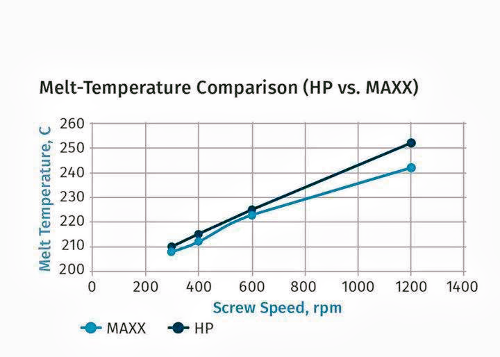
We tested the ZSE-27 HP (27 mm screw, 1.5/1 OD/ID ratio) and ZSE-27 MAXX (28.3 mm screw, 1.66/1 OD/ID ratio). In both cases, the feed capacity was the limiting factor. The 1.66/1 OD/ID ratio model had a lower melt temperature due to reduced specific energy per kg and the deeper flight design.
LDPE powder with a 12 MFI was processed on both the ZSE-27 HP and ZSE-27 MAXX. The 1.66/1 OD/ID ratio allowed more material to enter before feed restriction occurred. The feed rate increased by about 20%, which aligns with the higher free volume of the 1.66/1 OD/ID design. However, above 800 rpm, the feed rate increase was less noticeable. This is likely due to a “propeller” effect at higher speeds.
With the 1.66/1 OD/ID ratio, even at higher throughputs, melt temperature stayed lower due to reduced specific energy input and milder mixing effects from the helical geometry.
We also ran tests on the ZSE-27 MAXX (1.66/1 OD/ID) using 2 MFI PP resin to compare melt temperatures across different melt zone configurations. In the “aggressive” melting zone, melting is finished by barrel 3 (12 L/D). In the “extended” melting zone, melting is finished by barrel 4 (16 L/D). After melting, we used a single set of kneading blocks to isolate the melting zone effects.
The experiment used a low-pressure discharge die to minimize pressure’s impact on melt temperature. Melt temperature probes were positioned flush and immersed. We tested at various speeds and screw speeds to observe changes.
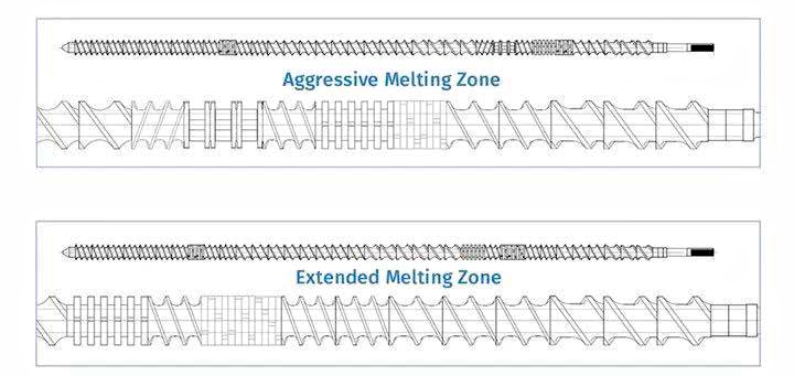
Experimental data were collected using a ZSE 27 MAXX twin-screw extruder (28.3 mm screw, 1.66/1 OD/ID ratio). The trials involved 2 MFI PE pellet resins, optimized temperature profiles, and varied screw speeds. The melt temperature in the aggressive design was consistently higher than in the extended zone design.
The aggressive melting zone uses neutral/wide-pan kneading block elements and reverse elements to fully melt the polymer by barrel zone 3. This design shortens the L/D, creating space for other operations (e.g., side feeding, mixing, or devolatilization) in the second half of the process.
In contrast, elongated screw designs with narrow-disk kneading block elements apply lower shear stress to the polymer, causing it to melt more slowly. Extending the melting zone helps reduce melting temperature and shear stress exposure.
After melting, individual kneading blocks are partially integrated into the screw design to limit the heat rise during mixing. The experiment also optimized the temperature profile and tested various screw speeds. Data in the melting temperature chart was collected with a handheld device.
In each case, the melt temperature for the aggressive design (10°C to 30°C) was much higher than for the extended zone design. It is worth noting that the temperatures measured by immersion probes (sometimes 20°C to over 40°C) are significantly higher than those measured by flushed melt probes. Apparently, when the melt probe is not fully immersed in the polymer melt, the melt temperature reading is affected by the metal adapter set point – lower than actual and not accurate.
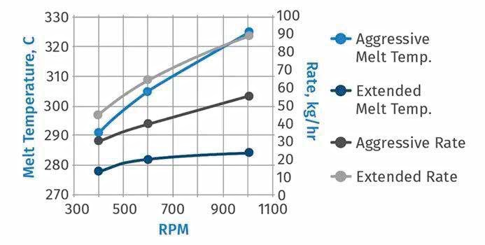
The achievable rate for both designs is also maximized by targeting 85% of the operating torque and increasing the rate until this threshold is reached. The extended melting zone design results in higher production rates and lower melt temperatures than aggressive screw designs. Comparing the two melting zones (active and extended) shows that the active melting zone leads to a significant temperature increase and lower achievable productivity compared to the extended melting zone. The higher temperatures inherent to aggressive screw designs can also lead to significant degradation, as evidenced by smoking and discoloration at increased screw speeds.
Other factors affecting the melt temperature
The screw design in the melting zone directly affects the melt temperature, which is of great significance. The temperature set point in this zone will also affect the melt temperature, and perhaps counterintuitively, a higher set point will generally result in a lower melt temperature. Therefore, in this study, the opposite temperature profile (higher temperature setting in the first part of the process) was chosen to reduce the increase in melt temperature associated with the melting zone.
In addition to melting, obviously the screw must be designed to melt and mix without causing excessive shear. Using wide kneading blocks and reverse elements for mixing will result in more energy being transferred to the process and further increase the melt temperature, which must be considered when designing the screw.
Often overlooked, the pressure generated at the TSE extrusion site also increases the melt temperature. The more front-end restriction, the higher the pressure and corresponding melt temperature. The temperature rise associated with the front-end design can be estimated as follows:
∆ T (C) = ∆ P (bar) ÷ 2
∆ T = Temperature change (C)
∆ P = Pressure change (1 bar = 14.503 psi)
For example, if the processing rate of TSE is 500 kg/hr and the mold pressure is 40 bar (580 psi), the associated melt temperature increase may be 20°C (ΔT = 40÷2).
This formula should be informative, if not necessarily accurate, since screw speed, exit screw element geometry, temperature set point, and recipe viscosity are all factors in the final melt temperature. The key is that front-end design must be considered when managing melt temperature in a co-rotating twin-screw extruder.
Source of content: From ptonline, author Charlie Martin (Leistritz), Xintec Translation
Disclaimer: (Part of) the data, charts or other content in this article comes from the Internet or other publicly published materials, and is for readers’ reference, communication, and learning only, and does not involve any commercial behavior or purpose. The copyright belongs to the original author and original source. If the copyright owner believes that this article is suspected of infringement or other problems, please contact us and deal with it in time.

