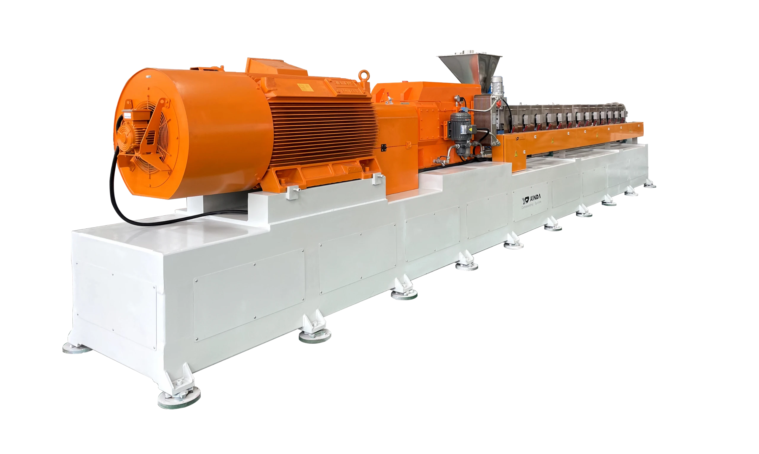
In recent years, China’s twin-screw extruders have continued to develop, occupying a relatively high market share in the international market. They are widely used in engineering plastics, rubber, food, paper, and other industries.
Especially in the engineering plastics industry, the twin-screw extruder has become the main equipment for plastic modification, reinforcement, and blending extrusion.

The twin-screw extruder is divided into two key parts: “extrusion” and “transmission.” The “extrusion ” part is the key to “guarantee quality,” and the “transmission ” part is the key to “improve efficiency” and “guarantee quality.” The twin-screw’s technical progress is marked by the replacement of the torque distribution box, which shows its importance. Let’s talk about the “transmission” part of the extruder today.
The transmission is the core part of the twin-screw extruder. Like a car engine, it can provide sufficient power to ensure sufficient output. Therefore, a strong transmission system is required to provide power to improve extrusion efficiency.
In the twin-screw extruder, the power is reflected by the rotational movement of the screw elements. The kinetic energy in the rotational movement is converted into torsional force. The greater the torsion, the more materials will be conveyed, which means the high-torque transmission system provides power to achieve high output.
The transmission system has two representative typical structures: a parallel three-axis gear structure and a double-sided symmetrical drive gear structure.


Figure 1 is a schematic diagram of the parallel three-axis gear structure. Power is transmitted in parallel to the two output shafts, among them, the output shaft A bears 50% torque. Because the A-axis has enough space, and the strength and rigidity safety coefficient is high, it is safe. Output shaft B also receives 50% of the torque, however, the B-axis is limited by the center-to-center dimension space, and the gear size is relatively small, which limits the output torque, making the B-axis a weak point in the gearbox, and also limits the output torque of the transmission structure.
In order to increase the torque of the B-axis, the improved structure designs two sets of gear transmissions on the B-axis (as shown in Figure 2). The torque carried by each set of gears is reduced from 50% of the torque of the original single set of gears to 25%, so that the total output torque of the gears is doubled compared with that of the single set of gears, achieving high torque output.

Schematic diagram of the transmission principle of the parallel three-axis distribution scheme.
The advantages of this scheme are simple structure, convenient assembly, low cost, and the torque of the system is improved by reducing the load of the gear; However, during the parallel transmission process of the power of this structure, the B-axis will always bear a large load (as shown in Figure 3), and the B-axis will always bear the force in the same direction during the rotation process, that is, the bending-torsion joint action (symmetrical cyclic stress). The force borne by the bearing on the B-axis increases with the increase of its output torque, so that the bearing will reach the life limit after 20,000 hours of force wear, so the life of the gearbox is restricted by the B-axis bearing.
Second, and the key point, because the B-axis always bears a large load, the wear of the bearing is accelerated, causing the radial runout of the B-axis to increase until it fails, making the system an unstable power system.
Fig. 4 is a schematic diagram of a double-sided gear symmetrical transmission structure. The output shaft A in this structure is the same as the previous structure, which has sufficient dimensional space, and has a large safety factor of strength and rigidity; the output shaft B is also limited by the center distance and has the problem of limited size. The solution of this structure is to divide the power into upper and lower two sets of gears, and drive the B axis symmetrically from the upper and lower directions, which not only reduces the load at the meshing point of the upper and lower gears by half, but also improves the torque load capacity, thereby doubling the feeding amount, effectively Improve production efficiency, and make the radial force on the B-axis cancel each other to zero. As shown in Figure 5, the gear of the B-axis is only subjected to tangential force, forming a perfect couple drive, that is, a pure torque output shaft, which eliminates the bending stress on the B-axis (only subject to torsion, that is, unidirectional cyclic stress).


Not only that, the more prominent features of this structure are: the load on the radial bearing on the B-axis is completely eliminated, the B-axis bearing will never wear out theoretically, and the service life is much longer than that of structure 1, which can reach 72000h (about 10a). Since then, the history of the rotation accuracy of the B-axis deteriorating with the running time has been changed.
This structure not only achieves high torque output, improves production efficiency, but also increases service life. More importantly, it ensures the stability of the torque distribution system and the consistency of product quality. The bearing on the output shaft B is not subjected to radial force. , no wear, no change in radial runout, no radial runout of the screw shaft, which can ensure the long-term stable and continuous operation of the entire system, that is, the gap between the screw and the barrel will not be uneven Changes, the residence time of the material in the barrel will not be uneven, thus ensuring the stability of product quality. Doubling the torque can greatly increase the feeding amount, which is the guarantee for doubling the production efficiency.
However, the disadvantages of this structure are: that the structure is relatively complicated, the processing precision is high, the assembly is difficult, and the manufacturing cost is relatively high.
The application of this transmission structure has the following great significance for the progress of extrusion technology:
- Provide stable and reliable power for the extrusion system
- With a higher torque output, a higher feeding amount can be achieved, and the effective length of the screw is also increased to achieve more uniform distribution and dispersion mixing;
- It provides reliable power for precise extrusion and efficient mixing;
- Higher output speed and smaller screw gap can be realized.
Source of content: 《Key Technology of Twin-screw Extruder》, organized by Chain Plastic Network and edited by Xinda.
Disclaimer: (Part of) the data, charts, or other content in this article comes from the Internet or other publicly published materials, and is for readers’ reference, communication, and learning only, and does not involve any commercial behavior or purpose. The copyright belongs to the original author and source. If the copyright owner believes that this article is suspected of infringement or other problems, please contact us and deal with it in time.

